Audio Signal Phase 101
08/14/2013

So, what’s the deal with signal phase? What is it? Why does it matter? Should it matter? And what tools are available to deal with signal phase?
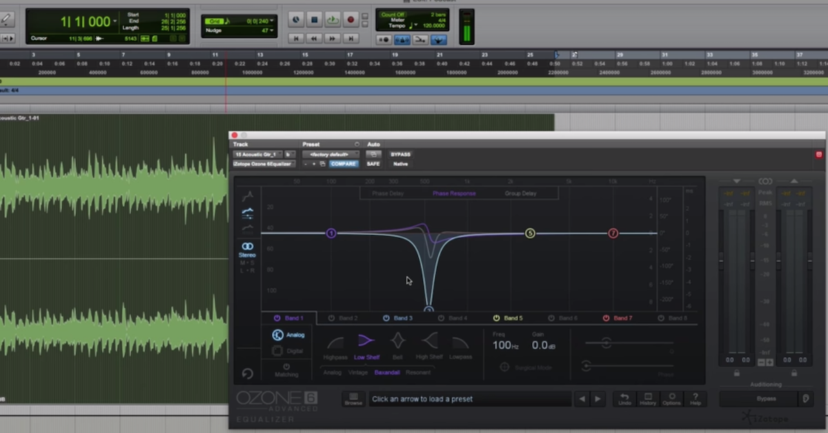
Many of us are familiar with signal processing tools like this equalizer, who’s primary function in almost all the controls are devoted to changing the amplitude of different frequencies in our signal. That way, if we look at the frequency response here of our input signal, shown in yellow, and the frequency response of our output signal shown in blue, we can see that the equalizer is primarily changing the amplitude of different frequencies.
But then when it comes to something like signal phase, how does that come into play? Well, many of us would assume that these buttons over here, these polarity inverting buttons, are really all you can do if you have problems with signal phase for control over the signal phase.
Well, what are these buttons really doing? Let’s look at an example. Here, I’m plotting a waveform of a simple sine wave as a very basic example. Let’s assume that this is our input signal to our signal processor that’s going to invert the polarity of our signal. What is the output signal going to look like? Well, it looks something like this. You can see wherever we had a peak in our input signal, we now have a valley in our processed signal. Here, we have a valley in our input signal, and now we have a peak.
That’s basically what the polarity inverting signal is going to do. How does this then relate to signal phase? Well, probably in some sessions for recording things that you’ve done, the terms “in-phase” or “out-of-phase” signals have come up. Maybe you’re listening and you said, “oh, maybe something weird is going on? Maybe we’ve got some signals that are in-phase or they’re out-of-phase.” Well, the question is are signals always either in-phase or out-of-phase? Or can they be kind of in-phase? Or maybe sort of out-of-phase? Well, let’s revisit this example.
Before, I had these two signals where the peaks and valleys lined up in this manner. Well, this isn’t always the case in our sessions. What if we have other signals where they don’t line up like that? Maybe they line up a little bit differently. Here, we have the peaks and valleys lining up differently between these signals. Wherever we had a peak, now we don’t have a peak or a valley. We’re at a different phase in our signal at this time period. So, the question is, are these the same signals? Or are these different signals? Well, one thing that you can do is consider if we shift this signal in time, we can see that the frequency of the signal is the same. So just by shifting it in time, we can see that peaks line up now, and our valleys line up. It’s this time delay that sort of conceptually relates these signals. But if we go back to the original one, they are not delayed in time. The difference between them is actually what would be called their “signal phase.” Let’s look at a different example. Are these signals the same? Is this red signal the same as the one on the previous slide? Well again, if I shift this one in time, you can see that our frequency is the same between the blue signal and the red signal. The difference is now, it took a much longer time delay to get the blue signal and the red signal to line up. That’s because the signal phase of the red signal started at a different phase than the previous red signal.
Let me give you a better example and describe what I mean by the signal phase.
I’m going to define it by using cyclical units, and these are degrees. Many people are familiar with this. You have something like zero degrees, and you can then go all the way up to 360 degrees. So I’m defining zero degrees as starting right here on this signal, and then where 360 degrees occurs is exactly where the signal is going to repeat for the next cycle. At 360 degrees, you’ve completed the whole way around the circle. That’s what people typically think of when it comes to degrees.
But then, you can look at this in terms of somewhere between zero degrees and 360 degrees. Half way through would be 180 degrees, shown here. You could also have 90 degrees, and also 270 degrees. And actually, more than that, you could also have everything in between zero degrees and 90 degrees as being possible definitions of the signal phase in our signals. So let’s revisit these previous examples.
So again, I’m saying that for this blue signal, a 90 degree phase shift will be if it started at this peak right here. So I’m representing that here. Again, the frequency of the signals are the same. The difference between these is the phase.
Here’s 180 degrees. So, 180 degrees corresponds to something similar to the polarity inverting.
Then we have 270, and these are the examples that I’ve shown you before.
So, the point I want to make at this point and revisit, is that phase is complicated. It’s not just that your signals are in-phase, or they’re out-of-phase. They could sort of be in-phase, or kind of be out-of-phase. And the thing is that your signal processors are going to affect phase in your signal.
What this is going to do is cause phase distortion. I’ll give you an example of this so hopefully you can get a better idea. The good news though, is that humans can not perceive signal phase differences in some cases. The bad news is that in all the other cases, when it does come up.
So, the question is, if you’re following to this point, is a signal phase shift basically just the equivalent of a time shift, just without the time shift?
That doesn’t seem so bad, right? But it’s actually even more complicated than that, because phase is frequency dependent. So your signal processors that are affecting phase might affect the phase of one frequency different than they affect the phase in a different frequency. So what happens if we have these phase shifts at different frequencies? What does that do to our signal?
Well, you might be familiar with the idea that phase is frequency dependent because of some kind of signal processors that are available. This is the Waves In-Phase processor.
What you see over here is for different frequencies, this processor is going to do some kind of phase shift that you see plotted on the y-axis for these different frequencies separately.
Why do you need to do that? Well, let’s look at it in another example. Before, I was using two signals that had the same frequency. But as I said, phase shifts are frequency dependent. So let’s look at two signals. On the top, we have the blue one with one frequency. On the bottom, we have one with a different frequency, because it repeats more often on the bottom than the repetitions on the top signal.
So, let’s say that we’re going to combine these signals. When they’re overlaid like this, but not added together, this is what they look like. Now, if I add these two signals together, the resulting signal, shown here at the bottom in green, is how they combine when these signals have this signal phase.
But let’s say I run these two signals, the red and the blue one, through a signal processor, and the signal processor changes the phase relationship between these frequencies.
So, my blue signal I’m having some kind of 90 degree phase shift so that it starts at this time, at the beginning time, at 90 degrees.
However, for my red signal, which is a different frequency, my signal processor might shift the phase now to 270 degrees, and it starts here. And that’s how these signals line up. Before they lined up when they started around the same time, now there are different amplitudes at the beginning time.
Well, what does this do to our output signal when these are actually added together? Let’s look at down here in the bottom right. This is what these signals look like when they’re combined. The question is then, is the green signal on the left different from the green signal on the right? Absolutely! In some cases, this is going to be perceivable, and in some cases, it’s not. But it’s something you need to be aware of, because of those other cases.
So, again, I want to revisit the fact that signal phase is complicated. It’s not just as simple as doing something like inverting the polarity. Also, phase is frequency dependent. Our signal processors will change the phase of frequencies differently.
So, then the question is, “are signal processors going to screw up your mix?” You’re a musician or a mixing engineer, and now that you’ve hopefully been able to understand that signal processors have the potential to screw up your mix, is it something you should be saying, “Oh, I just shouldn’t be using any signal processors” to?
Well, this is where linear phase processors come into play, and can be helpful.
There are many signal processors like this. This is the linear phase EQ from Waves. They also have other linear phase processors, like dynamics processors, and there are other companies that make them as well, this is just one example.
So, linear phase. What’s the deal with it? Why is it called linear phase? Well, if there’s linear phase, is there something that’s non-linear phase? And should you know the difference between them? Then, if these linear phase processors are so great, is there a drawback or trade-off by using these kinds of processors? Well, in order to understand what linear phase is and why it can be useful, it’s not very intuitive I think, because of the way that it describes the signal. It’s not very intuitive why it would be useful for music or as a mixing engineer.
So, let’s looks at this again. As musicians, as I said before, we’re more accustomed to or comfortable with looking at how the amplitude of our signal processor changes the amplitude of our signal.
So here, I’m just plotting frequencies. You can just think of this as low frequencies down here and high frequencies up here. Don’t necessarily get bugged out about the scale. Then, this is a low pass filter. Essentially, what this filter is going to do is allow low frequencies to pass unchanged. Basically a 0dB change in our low frequencies, and in our high frequencies, we’re going to decrease the amplitude of that, and as much as around 30-40dB of a decrease in amplitude.
As musicians, this is something that we come across a lot of times because we work with equalizers. The thing about equalizers or filters is that they also do things to the phase, as I discussed before. So, not only do you need to consider the amplitude of different frequencies, but then we can also consider how this filter, or equalizer, is going to change the phase of our signal.
So, this might be something for musicians or mixing engineers that you haven’t really come across. It’s not something you really think about. Maybe you’ve seen a processor like Waves In Phase, and so this might make a little bit of sense to you, or it might not.
So, this filter that I’m using, a low-pass filter, what it’s going to do is change the phase of these different frequencies by these different amounts. So the low frequencies, we’re changing the phase after it’s processed by very little. But then as we increase the frequency, you can see how around our mid-range frequencies, they’re being changed more. As we get up here, some of our higher frequencies are changed by different amounts.
So this is what would be considered a non-linear phase filter. The reason for this is probably more intuitive if we consider now, a linear phase equalizer or filter.
Again, I’m going to show you a low-pass filter, where the low frequency is not changed very much, but then we are decreasing the amplitude, or the magnitude, of the high frequencies up here.
If we look at our linear phase filter, we can see that it’s basically a straight line that goes from low frequencies that are changed by a little amount, up to high frequencies. That’s different than the non-linear one where it had these curvy shapes to them, and even this discontinuity up here.
So here’s our linear phase one. Now, what’s the deal with linear phasing, and why is that useful? Why should it matter? You’re still having the low frequencies change by one amount, and mid frequencies change by a different amount, and high frequencies change by an even larger amount, and all the frequencies in between are being changed by different amounts. Why is that a good thing or a bad thing? I’m going to provide another example to show why if the phase is being changed in a linear fashion, why that’s actually a good thing when it comes to the phase relationship between different frequencies. So here, in this example, I’ve plotted four different frequencies.
You have the green one, which is our lowest frequency, because it repeats less often than the other ones. Then the one a little bit higher is the blue one. Then you have the red one here, and then the black one, which is our highest frequency.
If you look at how these are lined up together, if you look at one time where the phase is in our green signal, this is just arbitrarily selecting at a certain time, for our green signal, you see that the phase is at 90 degrees. Then, if we increase the frequency of our signal just a little bit, and that’s our blue example, You see that at this time period, the phase is a little bit beyond 90 degrees. For the blue signal, 90 degrees is up here, but now we’re going a little bit beyond 90 degrees, closer to 180 degrees.
If we increase our red signal a little bit more, you see that the phase is even further beyond 90 degrees than the blue one. And then finally, black, which is our highest frequency that I’m plotting here, that we’re getting even closer to 180 degrees at this period of time.
So, what’s going to happen, if during processing, we shift the phase of each of these frequencies in a linear fashion, I’ll plot down here what ends up happening.
What ends up happening is the equivalent of a time shift in our signal where when you overlay them, the signal peaks and valleys still correspond at the exact same times between the different frequencies in our processed version down here compared to the unprocessed version at the top.
So if our processor shifts the phase in a linear fashion, essentially what happens is that the phase relationship between our signals is maintained, and not distorted. So that was the example I showed you before, where you had the red and the blue overlaid on top of each other, and if our signal processor messes up the signal phase, then we end up with signal that has some phase distortion.
But if we use a linear phase signal like this, where for increasing frequencies, we’re just increasing a little bit more and a little bit more for each of these frequencies in a linear fashion, the result is just the equivalent of a time shift in our signal. So, here’s our time delay that I’m showing.
So, when it comes to linear phase signals, what you need to know is that the signal processing of these linear phase filters or compressors results in a constant time shift for all frequencies. That means that the relationship between the frequencies is not distorted. The main trade-off is a time delay, or essentially latency that’s built into these kinds of filters.
I guess at this point, I just want to conclude with the question, “when are linear phase processors useful?” Well, the main thing is when you don’t want to screw up phase relationship between different frequencies. When you don’t want those to be distorted. So you’re likely saying, “I always want that to be the case!” Like I said before, sometimes a phase distortion isn’t even perceivable, but at the same time, you need to be aware that there’s latency that can come in, and if you don’t deal with the latency properly, if you delay one signal compared to another one, and you don’t delay another one, you’re essentially just going to be having more phase problems because of the latency.
So the places where I think that it’s most useful is on the master buss, because at that point, all your signals are being added together anyway, and hopefully you’ve got things set up properly in your mix where the signals are lined up properly to begin with, so at the master stage, it would be a terrible thing if you have some phase distortions going on.
So, thinking of something like linear phase equalizers or compressors, that would be a good place for it. But you can also use it at other stages in your mix if you’re able to properly compensate for latency.
So in conclusion, I hope that you’re able to get a better idea about signal phase and understand it’s actually pretty complicated when it comes to signal processors and using them as a musician or as a mixing engineer. At the same time, it shouldn’t be something that, now that you know about them, hopefully you don’t fear because there are tools available that you can apply at different places in your mix in order to ensure that you don’t have any issues related to signal phase distortion.
So, with that, I guess if there’s any questions, feel free to shoot me a message, and post comments, and I’ll try my best to answer any of those questions if something wasn’t clear.
Elevate Your Ears